Circuit Design
Required parts
- 1 ESP32
- 2 resistors (1 x 220 Ω and 1 x 10 kΩ)
- 1 LED
- 1 push button
- 2 breadboards (ESP32 dev boards are usually too large to fit on a single breadboard)
- jumper wires (male to male) or a “hook-up” wire spool set (22 AWG)
- a wire stripper (in case you use spools of wire)
Wiring diagram
You can also get by with just one breadboard, by running the wires under the ESP32 board. But to make the schematic easier to read, I preferred to wire the components on two breadboards.
On my side, I used a 456 holes breadboard which has 6 holes per column and which allows to put all the components on a single breadboard.
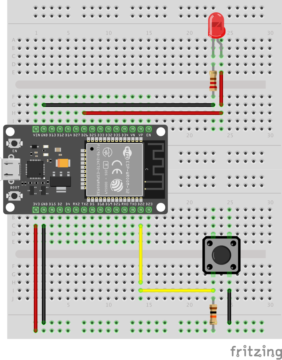
Here are the control pins used:
- GPIO 22 is connected to the power line of the push button
- GPIO 26 is connected to the anode of the LED
Note that I also used a 10 µF electrolytic capacitor between the EN pin and the ground, but it is only there to fix a manufacturing defect of my ESP32 board which does not automatically put itself in flashing mode when I want to upload a new program through the USB port.
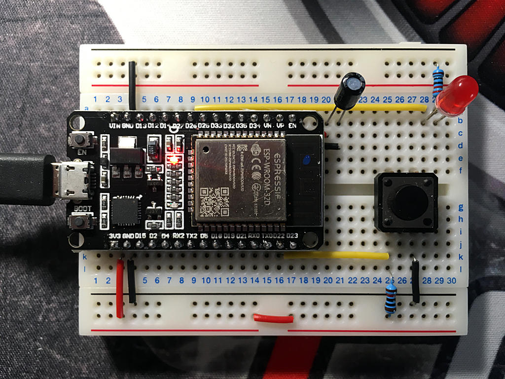
This problem is common on boards that are not made by Espressif itself, and I found this trick here:
[SOLVED] Failed to connect to ESP32: Timed out waiting for packet header
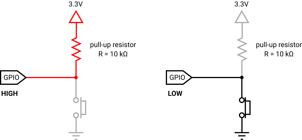
Pull-up resistor
You can notice that we’ve fitted the push button with a pull-up resistor. Let’s see why…
The digital pin to which the button is connected (GPIO23) must always be able to read a HIGH or LOW signal. And this signal must be able to be inverted depending on whether or not the button is pressed. Above all, however, care must be taken to ensure that this signal is not floating, otherwise the behaviour of the circuit may become erratic. And this is precisely the role of a pull-up or pull-down resistor.
A pull-up resistor is used to keep the pin in a default HIGH logic state by connecting it to the 3.3V supply line. A pull-down resistor does exactly the opposite and keeps the pin in a default LOW logic state by connecting it to ground. It is important to specify that this is not a specific type of resistor: it is a common resistor. Its place in the circuit gives it this name because of the function it performs.
I used a pull-up resistor here. In this way, the button status reading pin is kept in a default HIGH state and, when the button is pressed, its state will change to LOW.
Why use a 10 kΩ resistor? Does this value matter? Yes and no… in fact we usually use a resistor between 4.7 kΩ and 100 kΩ. The lower you go down to 4.7 kΩ, the more you increase the leakage current, which therefore wastes energy. The closer you get to 100 kΩ, the greater the risk of interfering with the internal circuitry of the microcontroller, causing erratic detection on the reading pin. I suggest going with 10 kΩ because they are common resistor values and people reading your schematic will be more likely to understand that it’s just a pull-up resistor.
Most of the ESP32 pins have internal pull-up (and pull-down) resistors, except for the following pins, which are input-only: GPIO 34, GPIO 35, GPIO 36 and GPIO 39. It may therefore appear unnecessary to add an external pull-up resistor on the reading pin of the push button. Indeed, to activate the pull-up resistor on the GPIO 22 pin, simply initialize it as follows:
pinMode(22, INPUT_PULLUP);
But it can happen that we forget about this specificity and simply initialize it with:
pinMode(22, INPUT);
Unfortunately, this oversight has a high chance of damaging your board. So, as a precaution, I still preferred to add an external pull-up resistor to avoid an unpleasant surprise.