ESP32
Light Sleep
Deep Sleep
Hibernation
Experimenting with ESP32 sleep modes
Tuesday, March 17, 2020
Required Parts
To follow this tutorial you need the following parts:
- 1 ESP32
- 5 resistors (1 x 220 Ω, 2 x 100 Ω and 2 x 10 kΩ)
- 3 LEDs
I used a red, a yellow and a green one, but you can use the LEDs of your choice. You’ll just have to think about adapting the value of the protection resistors that you’ll add to them in series. - 2 push buttons
- 2 breadboards
- Jumper wires (male to male) or a “hook-up” wire spool set (22 AWG)
- a wire stripper (in case you use spools of wire)
Wiring Diagram
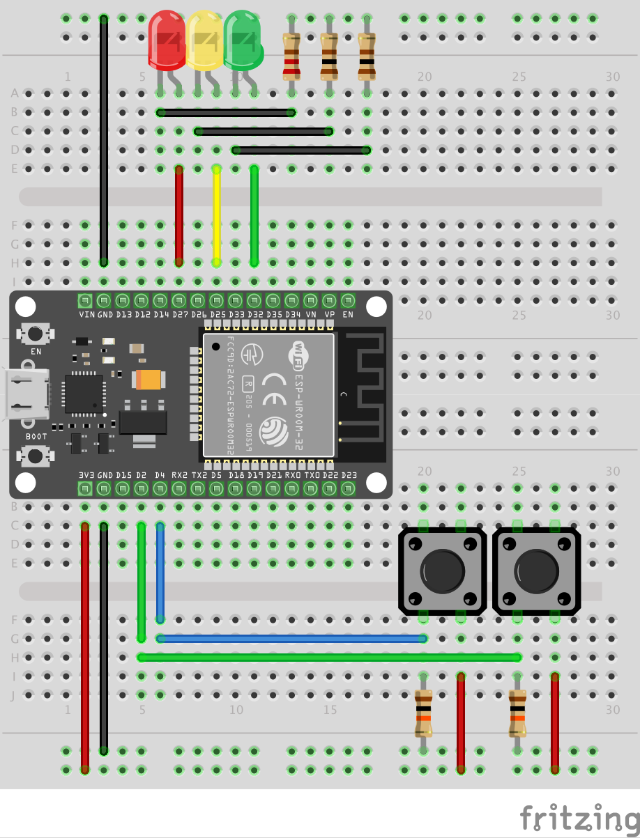
Be sure to use the following pin assignment:
- GPIO27 is connected to the anode of the red LED
- GPIO25 is connected to the anode of the yellow LED
- GPIO32 is connected to the anode of the green LED
- GPIO4 is connected to the ground line of the left button (LED shifter)
- GPIO2 is connected to the ground line of the right button (sleep trigger)
Use Of Pull-Down Resistors
You can notice that we’ve fitted each button with a pull-down resistor. Let’s see why…
The digital pins to which the buttons are connected (GPIO2 and GPIO4) must always be able to read a HIGH or LOW signal. And this signal must be able to be inverted depending on whether or not the corresponding button is pressed. Above all, however, care must be taken to ensure that this signal is not floating, otherwise the behaviour of the circuit may become erratic. And this is precisely the role of a pull-up or pull-down resistor.
A pull-up resistor is used to keep the pin in a default HIGH logic state by connecting it to the 3.3V supply line. A pull-down resistor does exactly the opposite and keeps the pin in a default LOW logic state by connecting it to ground. It is important to specify that this is not a specific type of resistor: it is a common resistor. Its place in the circuit gives it this name because of the function it performs.
I preferred to use pull-down resistors here. In this way, the button status reading pin is kept in a default LOW state and, when the button is pressed, its state will change to HIGH.
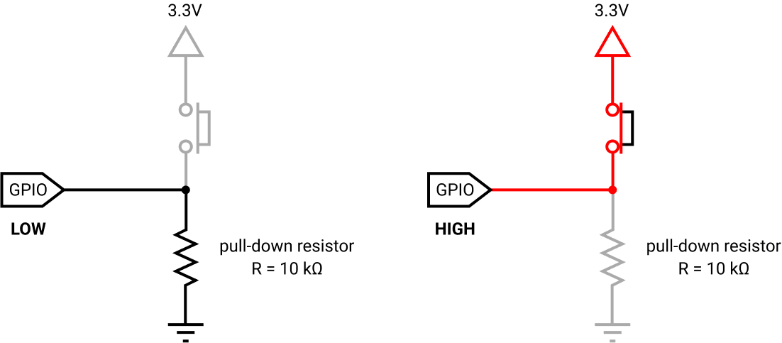
In such case, the small amount of current flows from the 3.3V source to the ground using the closed switch and pull-down resistor, hence preventing the logic level pin to getting shorted with the 3.3V source.